There are good step by step zoning documents out on the internet, so I assume this post will be a success. This post will explain how to do Fibre Channel Zoning using any type of Brocade Fibre Channel Switch. In this case, I am zoning in a Dell Compellent SAN, but these steps basically apply for any type of SAN.
Fibre Channel Zoning for Dell Compellent
After Installing your FC Switch, Login to it by going to the IP address in a web browser. It requires a specific version of Java and I have found it works best in Firefox than any other browser.
Once logged into the Switch, you should be presented with the Main Switch Admin page that will look something like this. (Each model varies slightly):

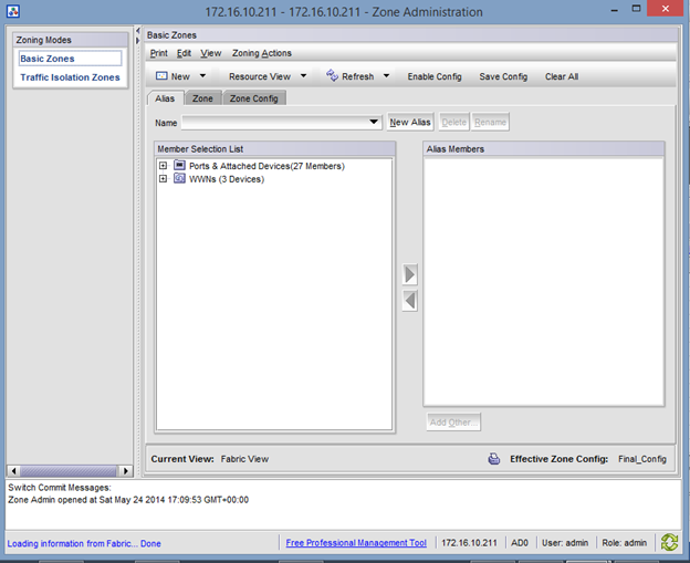
Click Configure at the top of the Screen and Choose “Zone Admin”. A new Window will appear and look like this:

Here is where all the magic happens. In FC Zoning, the goal is to create “VLAN-Like” objects called zones that contain the WWNs of your Server and Storage HBAs.
Since I am configuring this for a Compellent SAN, the first thing I need to do is create an Alias for all the Physical WWNs. To do this, I click on the Alias Tab and Select the “New Alias” Button.

Give your Alias a descriptive name, like SAN_Phy_WWNs_ Alias.
Expand the WWN’s on the lefthand side. Keep this window on the right side of your screen with the Compellent Storage Center GUI opened on the lefthand side with the Fibre Channel IO cards expanded so you can see their WWNs.

Add all the Physical WWNs you see in the switch that match up with the Physical WWNs on the Compellent SAN. (Physical WWNs on Compellent are the Green objects).
If you have a two port card, you will only see two Physical WWN’s (Per switch).
After you have added the two Physical WWNs to this alias you created, you will need to do this exact same thing on your other switch, only this time you will use the OTHER Compellent Physical WWNs you see in the list.
When finished, create a new alias and call is something like “SAN_Virt_WWNs_Alias”.
This time you will follow the same steps as above but you will be adding the Virtual WWNs of the Compellent into this alias. The Virtual WWNs are the ones in blue. Again, if you have a two port FC card, there should only be two WWN’s PER SWITCH. Repeat this process on your other switch for the other Virtual WWNs.
Next we create two Zones. One Zone that includes the Alias of the Physical WWNs and one zone that contains the Alias of the Virtual WWNs. TO do this, click on the Zone tab and select new Zone.

Name the Zones something like “SAN_Virt_WWNs” and “SAN_Phys_WWNs”.
In one zone add JUST the “SAN_Virtual_WWN_Alias” Alias, and in a new Zone and JUST “SAN_Phys_WWNs_Alias”

Now for the Servers- When you plug in a server into the FC switch, you will see a new WWN.

You need to go to the Alias Tab and create a new Alias and name is something like: “ServerName”.
Expand the WWN and add the Second-Level WWN object to this Alias.

Next, go to the Zone tab and Create a new zone, something like “Servername+SAN_WWNs”.
Add the Server Alias you created PLUS the “SAN_Virtual_WWNs” Alias.
You will need to make sure each Server you connect to the SAN has It’s server alias + The SAN’s Virtual WWN’s.

Finally, click on the Zone Config Tab and create a new Zone Config. Add all the Zones you created into this Zone Config Tab. This is basically a big file will all your settings.

Click on Save Config at the top and wait about 30 seconds for the changes to be saved. You’ll see a success message in the bottom log screen.
The select Enable Config. Wait another 30 seconds for the settings to be enabled and take effect.
To recap, these are the aliases and zones you will need to create:
Compellent_Phy_WWNs: Alias
Compellent_Virt_WWNs: Alias
Compellent_Phy_Alias: Zone
Compellent_Virt_Alias: Zone
ServerWWN+Compellent_Virt_WWN: Zone
Add all those to your zone config.
If you found this article to be helpful, please support us by visiting our sponsors’ websites.


 By default, the password expiration on the local root account in the vCSA is set to 90 days after the password has been changed. This typically occurs at first boot. If the password is not changed on installation, there is a 90-day period before expiration.Email addresses configured in the Admin tab in the VAMI (